


 This chapter in pdf-format: www.researchgate.net/publication/321340138
26
Impedance Tomography
|
N.B. This chapter describes works, where the calculation of the inverse solution in impedance tomography is based on the
generally used Sheffield data collection system suggested by Brown and Segar (1987).
However, subsequent research: Kauppinen, Hyttinen, & Malmivuo, 2006 has shown, that the solution of Brown and Segar is not correct.
Therefore the information given in this chapter on the measurement sensitivity distribution in impedance tomography is erroneous.
References:
Kauppinen, P., Hyttinen, J. & Malmivuo, J. Sensitivity distribution visualizations of impedance tomography measurement strategies.
International Journal of Bioelectromagnetism, 2006, Vol. 8, No. 1, pp. VII/1 - VII/9
The aforementioned publication of Kauppinen, Hyttinen and Malmivuo may be downloaded in pdf-format from Researchgate: |
The spatial resolution of the impedance measurement may be enhanced by using an array of electrodes around the volume conductor of interest. Electric current may be fed consecutively through different available electrode pairs and the corresponding voltage measured consecutively by all remaining electrode pairs. In this way it is possible, by using certain reconstruction algorithms, to create an image of the impedance of different regions of the volume conductor. This imaging method is called impedance imaging. Because the image is usually constructed in two dimensions from a slice of the volume conductor, the method is also called impedance tomography and ECCT (electric current computed tomography). Thus impedance tomography is an imaging method which may be used to complement x-ray tomography (computer tomography, CT), ultrasound imaging, positron emission tomography (PET), and others. The reader may find more information about the modern medical imaging methods from such references as Krestel (1990), Webb (1992), and Wells (1982).
In creating an image, it is desirable to limit the region which is involved and to know the geometry of this region. In general, this is known accurately only if the energy signal proceeds linearly. This condition is satisfied for x-rays and for nuclear radiation. It is also true in ordinary photography with the addition that the light rays bend in the lens in an accurately known way. If the radiating energy proceeds along an unknown path, or if it proceeds from the source to the target via several paths (i.e., through a large volume), it is not possible to create an accurate image. As examples of this in photography (or vision), one may mention the halo around the sun or the mirage.
In impedance tomography the fundamental problem in the image reconstruction is that, in a general case, the electric current cannot be forced to flow linearly (or even along a known path) in an inhomogeneous volume conductor. Since there are no sources within the volume conductor (the sources all lie on the bounding surface in the form of applied currents) then the potential field, Φ, must satisfy 
 (σ Φ) = 0 and only a limited class of functions can satisfy this. When σ is a constant then Φ satisfies Laplace's equation and, thus, even fewer functional forms are available (such as Legendre polynomials, etc.). As was shown in Section 11.6.9, it is possible to create a linear current field in a homogeneous volume conductor of arbitrary shape. In the sense of impedance tomography such a volume conductor is, however, of minor interest, because its image would be 50% gray (i.e. uniform) throughout.
The accuracy of these images is not, however, limited by the size of the electrodes, as it is by the size of the focus of the x-ray tube and the detector in computer tomography. In impedance imaging, the image is blurred because in an inhomogeneous volume conductor the path of the electric current is not linear and in the general case it is not known accurately.
It should be noted that, though the basic purpose of impedance tomography is to reconstruct an impedance image from a slice of three-dimensional body area, it may also be used for a more accurate monitoring of some physiological parameter. Woo, Hua, and Webster (1992) presented an example of this kind of instrumentation for a more reliable infant apnea monitor. With the impedance tomography technique it is possible to concentrate the collection of impedance data more accurately to the lung area and thus to avoid the artifacts caused by the chest-wall movements.
In this chapter we briefly review some fundamental questions in impedance tomography. The reader may obtain more information from such excellent sources as Brown and Barber (1992), Hames (1990), and Webster (1990).
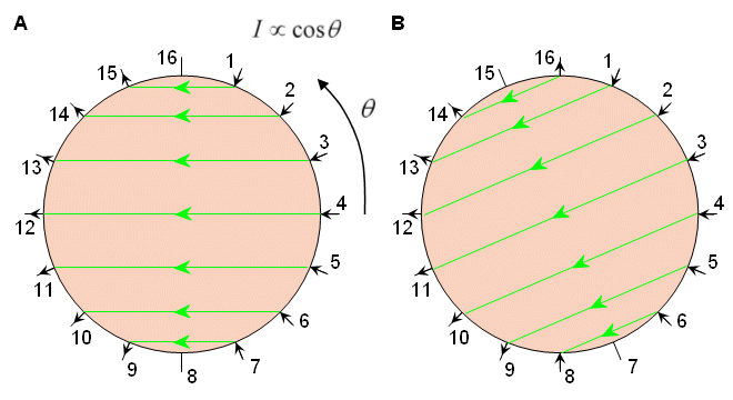
The current is first applied through electrodes 1 and 2 (Figure 26.1A). The current density is, of course, highest between these electrodes, decreasing rapidly as a function of distance. The voltage is measured successively with electrode pairs 3-4, 4-5, . . . 15-16. From these 13 voltage measurements the first four measurements are illustrated in Figure 26.1A. All these 13 measurements are independent. Each of them is assumed to represent the impedance between the equipotential lines intersecting the measurement electrodes. This is indicated with shading for the voltage measurement between electrodes 6 and 7.
The next set of 13 voltage measurements is obtained by feeding the current through electrodes 2 and 3, as shown in Figure 26.1B. For a 16-electrode system, 16�13 = 208 voltage measurements are obtained. Because of reciprocity, those measurements in which the current electrodes and voltage electrodes are interchanged yield identical measurement results. Therefore, only 104 measurements are independent. In the neighboring method, the measured voltage is at a maximum with adjacent electrode pairs. With opposite electrode pairs, the voltage is only about 2.5% of that.
(σ Φ) = 0 and only a limited class of functions can satisfy this. When σ is a constant then Φ satisfies Laplace's equation and, thus, even fewer functional forms are available (such as Legendre polynomials, etc.). As was shown in Section 11.6.9, it is possible to create a linear current field in a homogeneous volume conductor of arbitrary shape. In the sense of impedance tomography such a volume conductor is, however, of minor interest, because its image would be 50% gray (i.e. uniform) throughout.
The accuracy of these images is not, however, limited by the size of the electrodes, as it is by the size of the focus of the x-ray tube and the detector in computer tomography. In impedance imaging, the image is blurred because in an inhomogeneous volume conductor the path of the electric current is not linear and in the general case it is not known accurately.
It should be noted that, though the basic purpose of impedance tomography is to reconstruct an impedance image from a slice of three-dimensional body area, it may also be used for a more accurate monitoring of some physiological parameter. Woo, Hua, and Webster (1992) presented an example of this kind of instrumentation for a more reliable infant apnea monitor. With the impedance tomography technique it is possible to concentrate the collection of impedance data more accurately to the lung area and thus to avoid the artifacts caused by the chest-wall movements.
In this chapter we briefly review some fundamental questions in impedance tomography. The reader may obtain more information from such excellent sources as Brown and Barber (1992), Hames (1990), and Webster (1990).
The current is first applied through electrodes 1 and 2 (Figure 26.1A). The current density is, of course, highest between these electrodes, decreasing rapidly as a function of distance. The voltage is measured successively with electrode pairs 3-4, 4-5, . . . 15-16. From these 13 voltage measurements the first four measurements are illustrated in Figure 26.1A. All these 13 measurements are independent. Each of them is assumed to represent the impedance between the equipotential lines intersecting the measurement electrodes. This is indicated with shading for the voltage measurement between electrodes 6 and 7.
The next set of 13 voltage measurements is obtained by feeding the current through electrodes 2 and 3, as shown in Figure 26.1B. For a 16-electrode system, 16�13 = 208 voltage measurements are obtained. Because of reciprocity, those measurements in which the current electrodes and voltage electrodes are interchanged yield identical measurement results. Therefore, only 104 measurements are independent. In the neighboring method, the measured voltage is at a maximum with adjacent electrode pairs. With opposite electrode pairs, the voltage is only about 2.5% of that.
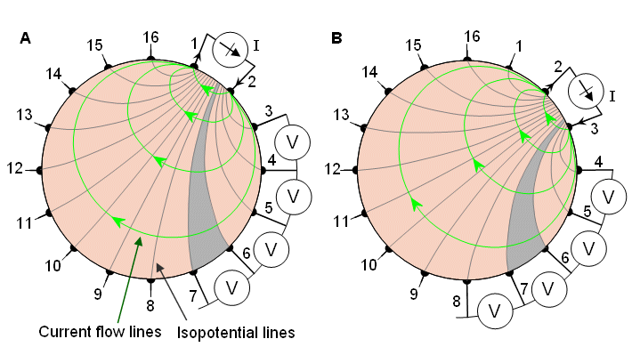
Fig. 26.1 Neighboring method of impedance data collection illustrated for a cylindrical volume conductor and 16 equally spaced electrodes.
(A) The first four voltage measurements for the set of 13 measurements are shown.
(B) Another set of 13 measurements is obtained by changing the current feeding electrodes.
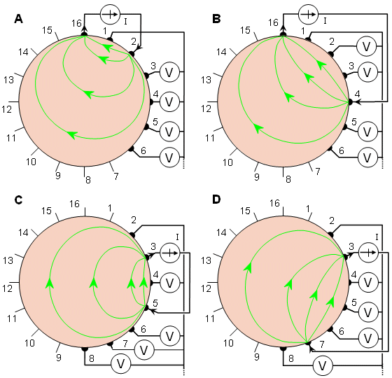
In the cross method, adjacent electrodes - for instance 16 and 1, as shown in Figure 26.2A - are first selected for current and voltage reference electrodes, respectively. The other current electrode, electrode number 2 is first used. The voltage is measured successively for all other 13 electrodes with the aforementioned electrode 1 as a reference. (The first four voltage measurements are again shown in Figure 26.2A.) The current is then applied through electrode 4 and the voltage is again measured successively for all other 13 electrodes with electrode 1 as a reference, as shown in Figure 26.2B. One repeats this procedure using electrodes 6, 8, . . . 14; the entire procedure thus includes 7�13 = 91 measurements.
The measurement sequence is then repeated using electrodes 3 and 2 as current and voltage reference electrodes, respectively (see Figure 26.2C). Applying current first to electrode 5, one then measures the voltage successively for all other 13 electrodes with electrode 2 as a reference. One repeats this procedure again by applying current to electrode 7 (see Figure 26.2D). Applying current successively to electrodes 9, 11, . . ., 1 and measuring the voltage for all other 13 electrodes with the aforementioned electrode 2 as a reference, one makes 91 measurements. From these 182 measurements only 104 are independent. The cross method does not have as good a sensitivity in the periphery as does the neighboring method, but has better sensitivity over the entire region.
The next set of 13 voltage measurements is obtained by selecting electrodes 1 and 9 for current electrodes (Figure 26.3B). When 16 electrodes are used, the opposite method yields 8�13 = 104 data points. The current distribution in this method is more uniform and, therefore, has a good sensitivity.
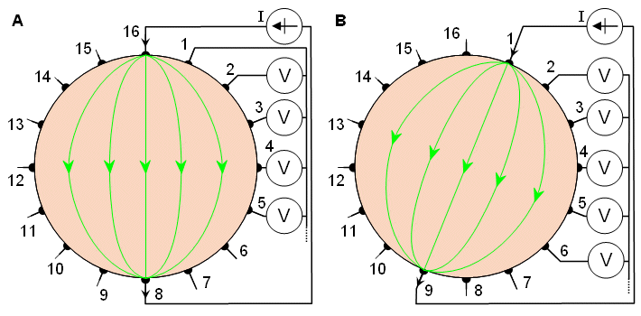
The voltages are measured with respect to a single grounded electrode. When one is using 16 electrodes, the number of voltage measurements for a certain current distribution is 15. The desired current distribution is then rotated one electrode increment (22.5 for a 16-electrode system; see Figure 26.4B). Thus 8 different current distributions are obtained, yielding 8�15 = 120 independent voltage measurements.
In the electromagnetic measurement of the electric impedance, as in pure electric measurement, the sensitivity distribution of the measurement is similarly proportional to the dot product between the electric current field in the volume conductor and the lead field of the voltage measurement. This holds true irrespective of whether or not the electric current in the volume conductor is generated through direct application of electric currents or is induced by a time-varying magnetic field, and whether the detector is a magnetometer or a voltmeter, respectively. In Figure 1.2B these principles of electromagnetic measurement of electric impedance were introduced briefly; they are presented in more detail below.
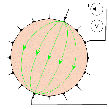
One way to utilize the electromagnetic connection in the electric impedance measurement is to feed the electric current to the volume conductor by means of electrodes on its surface, but instead of detecting the generated voltage with another pair of electrodes, the induced magnetic field is detected with a magnetometer. In this method the electric current distribution is irrotational (zero curl). As discussed in Chapter 12, the lead field of the magnetometer is tangentially oriented. The back-projection for impedance imaging can be made by first determining the electric current distribution in the volume conductor from the magnetic field measurements and thereafter the impedance distribution. Figure 26.5A illustrates this principle. Impedance images obtained with this method have not been published. Ahlfors and Ilmoniemi (1992) have published the electric current field change caused by an insulating cylinder placed in a saltwater tank, as measured with a 24-channel SQUID magnetometer.
The electromagnetic connection may also be used the other way around in the measurement of the electric impedance of the volume conductor. Due to the electromagnetic connection, the electric current may also be induced to the volume conductor by a time-varying magnetic field generated by a coil or a set of coils around the volume conductor (Purvis, Tozer, and Freeston, 1990). This gives an opportunity to create different kinds of current distributions compared to the feeding of electric current through electrodes. In this case the electric current field is solenoidal (zero divergence). This principle of measuring the electric impedance is illustrated in Figure 26.5B. Healey, Tozer, and Freeston (1992) published impedance images measured from a three-dimensional phantom. They used three equally spaced coils around a cylindrical phantom and measured the potentials by 16 equally spaced surface electrodes.
Note that because the sensitivity distribution of the electromagnetic measurement of the electric impedance is proportional to the dot product of the electric current field and the detector lead field, in both of these configurations, owing to the principle of reciprocity, the sensitivity distribution is the same, provided that similar coil and electrode structures are used.
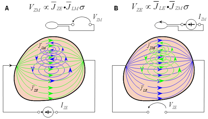
(A) Electric current is fed through electrodes, and the current distribution is detected with a magnetometer.
(B) Electric current is induced with a coil, and the induced voltage is measured with electrodes.An example of the reconstructed image is presented in Figure 26.6 (Woo et al., 1992). In this experiment, the impedance image was determined for two different phantoms that resembled the cross section of the human thorax. The phantoms were constructed by mixing agar powder and NaCl with boiling water. Figure 26.6A and C show the true images of the two phantoms. The reconstructed impedance images of these phantoms are shown in B and D, respectively. Figure 26.6E illustrates the scale for the resistivity image.
As a nonionizing and inexpensive method, electric impedance tomography is an interesting addendum to the various medical imaging methods. Though the image resolution of in-vivo studies is continuously increasing, it will theoretically remain lower than that of x-ray and ultrasound. This low resolution will certainly limit its application to that of monitoring, rather than to accurate anatomical imaging applications.
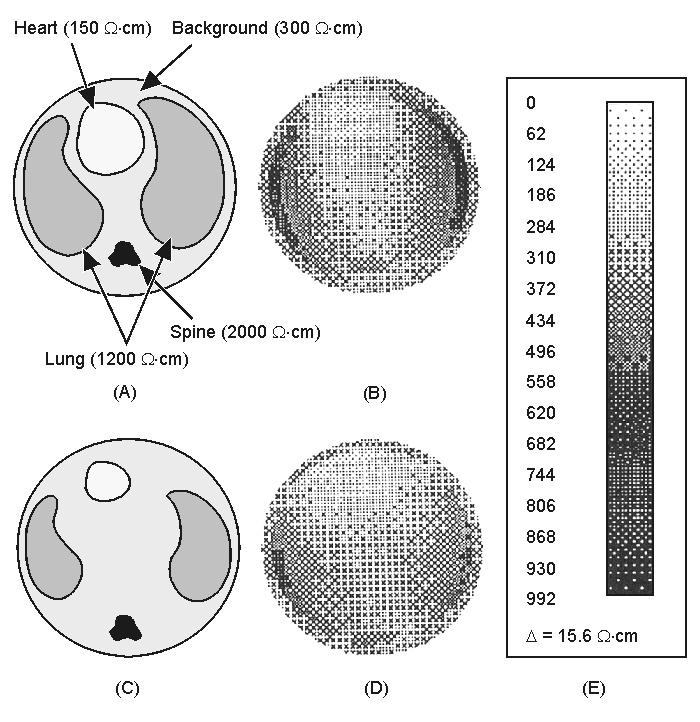
(A) and (C) True images of the physical phantom modeling the human thorax.
(B) and (D) Reconstructed images of A and C, respectively.
(E) Scale of resistivity images.Ahlfors S, Ilmoniemi R (1992): Magnetic imaging of conductivity. In Proc. 14th Annual Int. Conf. IEEE Eng. In Med. And Biol. Society, Paris, Vol. 14, ed. JP Morucci, R Plonsey, JL Coatrieux, S Laxminarayan, pp. 1717-8, IEEE, Piscatway, N.J.
Barber DC, Brown BH (1984): Applied potential tomography. J. Phys. E.: Sci. Instrum. 17: 723-33.
Brown BH, Segar AD (1987): The Sheffield data collection system. Clin. Phys. Physiol. Measurement 8(Suppl. A): 91-7.
Cheney M, Isaacson D (1992): Distinguishability in impedance imaging. IEEE Trans. Biomed. Eng. 39:(8) 852-60.
Cheng KS, Simske SJ, Isaacson D, Newell JC, Gisser DG (1990): Errors due to measuring voltage on current-carrying electrodes in electric current computed tomography. IEEE Trans. Biomed. Eng. 37:(60) 60-5.
Gisser DG, Isaacson D, Newell JC (1987): Current topics in impedance imaging. Clin. Phys. Physiol. Measurement 8(Suppl. A): 39-46.
Healey TJ, Tozer RC, Freeston IL (1992): Impedance imaging of 3D objects using magnetically induced currents. In Proc. 14th Annual Int. Conf. IEEE Eng. In Med. And Biol. Society, Paris, Vol. 14, ed. JP Morucci, R Plonsey, JL Coatrieux, S Laxminarayan, pp. 1719-20, IEEE, New York, N.Y.
Hua P, Webster JG, Tompkins WJ (1987): Effect of the measurement method on noise handling and image quality of EIT imaging. In Proc. Ninth Int. Conf. IEEE Eng. In Med. And Biol. Society, Vol. 2, pp. 1429-30, IEEE, New York, N.Y.
Purvis WR, Tozer RC, Freeston IL (1990): Impedance imaging using induced current. In Proc. 12th Annual Int. Conf. IEEE Eng. In Med. And Biol. Society, Vol. 1, pp. 114-5, IEEE, New York, N.Y.
Woo EJ (1990): Finite element method and reconstruction algorithms in electrical impedance tomography. Dept. of Electrical and Computer Eng., Univ. of Wisconsin, Madison, (Ph.D. thesis)
Woo EJ, Hua P, Webster JG, Tompkins WJ (1992): Measuring lung resistivity using electrical impedance tomography. IEEE Trans. Biomed. Eng. 39:(7) 756-60.
Brown BH, Barber DC (eds.) (1992): Electrical Impedance Tomography, 207 pp. The Institute of Physical Sciences in Medicine, York. (Clinical Physics and Physiological Measurement, Vol. 13, Suppl. A)
Hames TK (ed.) (1990): Proc. Meeting On Electrical Impedance Tomography, Copenhagen, 14th - 16th July 1990, 284 pp. European Community Concerted Action on Electrical Impedance Tomography, Brussels.
Krestel E (ed.) (1990): Imaging Systems for Medical Diagnostics, 636 pp. Siemens Aktiengesellschaft, Berlin and Munich.
Webb S (ed.) (1992): The Physics of Medical Imaging, 2nd ed., 633 pp. IOP Publishing Ltd, Bristol.
Webster JG (ed.) (1990): Electrical Impedance Tomography, 223 pp. Adam Hilger, Bristol and New York.
Wells PNT (ed.) (1982): Scientific Basis of Medical Imaging, 284 pp. Churchill Livingstone, New York.